Research Papers
Great Eastern Ramp
“God and Soldier we adore in time of trouble and not before. All things done and trouble righted God is forgotten and the Soldier slighted”
Anon from the War of the Roses 1485
THE GREAT EASTERN RAMP (BASED ON THE CHURCHILL MARK IV)
BUILDING THE MODEL
The greatest difficulty in modelling this unique vehicle was the dearth of information. Except for less than a dozen original photographs, many of which are very poor quality, the Great Eastern Ramp (GER) is shrouded in secrecy. When approached by the Canadian War Museum (CWM) to produce a 1:35 scale model of the GER in full ramp extended mode it was with some trepidation that the commission was accepted. Firstly, I am not a professional modeller and secondly, little background information was available. The Internet is a great source of information but not in this case. The few sources offered some nuggets but often referred to the CWM example. I contacted the Royal Engineers Museum in Gillingham, Kent but they had no information whatsoever. I was hoping to obtain a copy or drawings from a wartime manual, but nothing. Well, I did have full access to the real thing, courtesy of the CWM, albeit in its altered state. My best friend, another retired armoured officer, happened to be a graduate of the Royal Military College of Science in Shrivenham and has a mechanical mind and proved invaluable in brainstorming ideas of how the creature functioned. However, it was not until I accidentally discovered an old copy of The War Illustrated, Volume 10, Number 239, 16 August 1946 on eBay, that I saw the GER in all her glory. It was only a single cover photograph, (captioned, “One of Britain’s Wartime Secrets” – no kidding!) but it answered many of the questions I had about the operational vehicle. The usual photograph of the GER, often shown in books, is the prototype which differs from the production model.
During the museum’s annual maintenance period we received permission to examine the GER. We crawled over the vehicle inside and out following electrical conduits, cable lines and trackways until we felt we knew the operation of the vehicle as well as we could in the absence of a manual. So, armed with hundreds of first-hand photos, key Internet photos, a few other diagrams gleaned from books, eBay and the considerable help of my friend I began the project.
THE MODEL
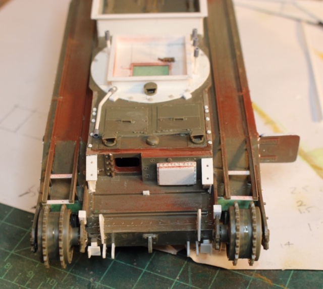
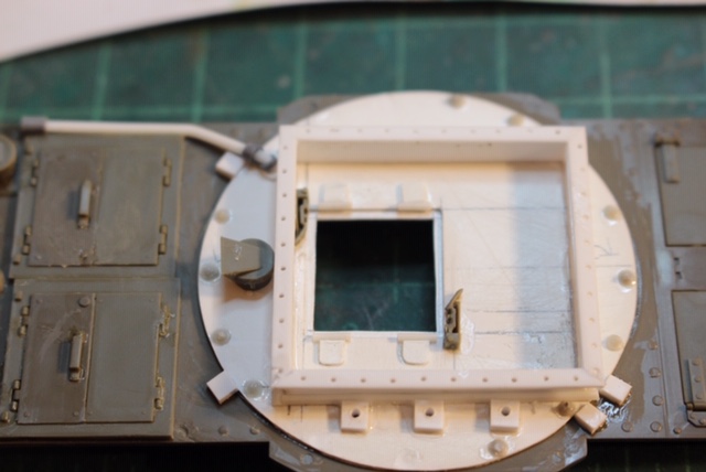
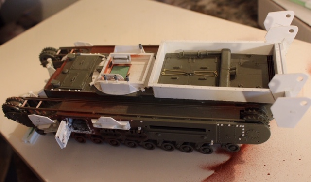
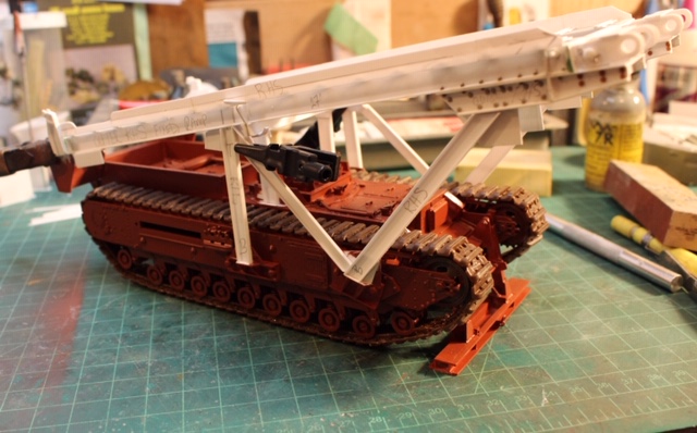
The AFV Club Churchill Mark III (Dieppe Raid) scale model was used as the platform for the conversion to the GER. The Mark III and Mark IV do not differ significantly on the exterior and I needed a Churchill with the tracks fully exposed. The suspension was modified to appear like the Mark VII otherwise it was a straight build. The major modification was the front face of the hull at the bow gunner’s position. On the museum’s GER this is covered over by an elaborate plate eliminating the function of bow gunner, so in the absence of any other information this was reproduced as it appears. This makes sense as the GER was going nowhere without an escort and protection, so the absence of a self-defence weapon did not appear to be an issue.
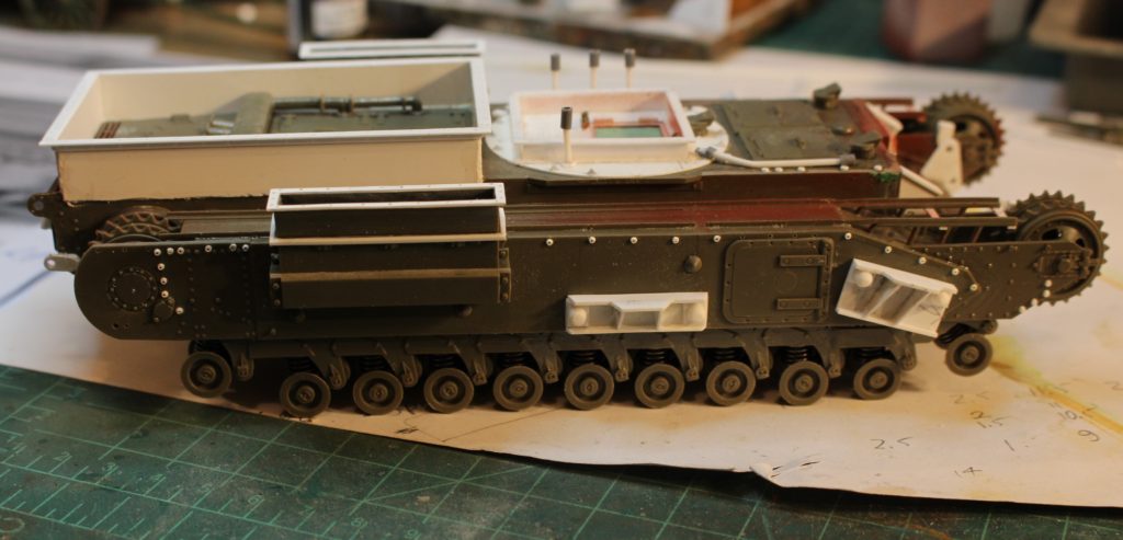
The next stage was to build the commander’s station and the wading trunk attachment frames. The frames would be present, but the actual trunks would not be included in the build as they would obscure many details of the commander’s area and the engine compartment not mention that and I had never seen a clear illustration of their placement.
The next challenge was to add the fixed ramp hull supports and they were fitted as closely as possible to real creature (in the hope they would remain true when the supports were added).
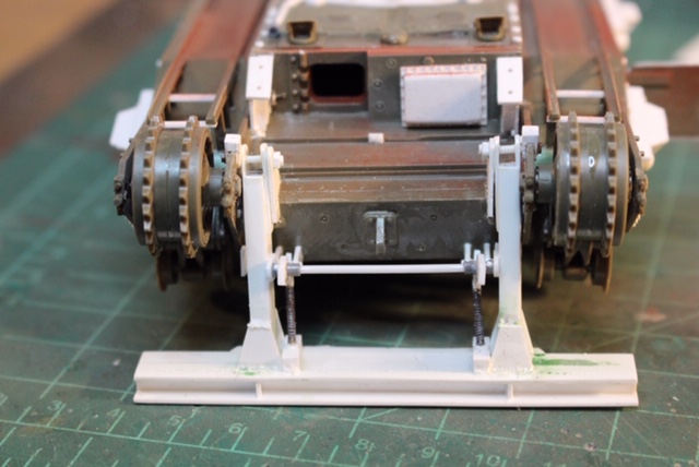
The front sprag or stabilizer foot was then constructed. This foot is attached to the bow and hinged. It is raised and lowered via a cable and I could not discover the actual method to perform this operation, so it was decided to have the cable go into the commander’s hatch – was there a hand winch or a mechanical winch? All I know is that the sprag is extremely heavy and on the CWM vehicle it is welded to the fixed ramp for safety. When in operation the sprag was lowered to the ground and locked into position supporting the extra weight of the front of the vehicle and would be unlocked manually.
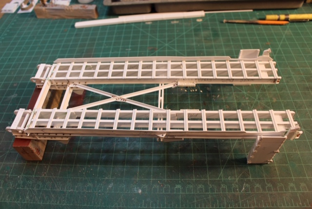
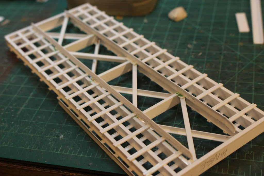
The biggest challenge for the build was the ramps, the supports and anchors. I chose to start with the entry ramp anchor. The pieces were scaled as much as possible then the rest was done using the Mark 1 eyeball.
After completing the anchor it was time to build the first of the three ramps. The smaller entry ramp was the easiest and I was able to experiment on techniques that would be used in the other two ramps. This ramp was not fully completed until I could access the real thing as I had made some incorrect assumptions initially. I had used the prototype as the basis, and this differs slightly from the production GER. Careful measurement was needed to ensure the pieces lined up and the fit was secure but workable.
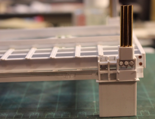
The hinge pins were plastic rod with brass wire cotter pins similar in appearance to the real thing. The A-frame was constructed from plastic rods and affixed to the ramp underside.
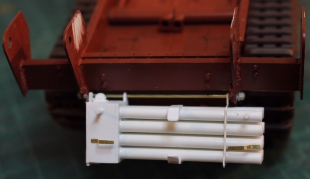
The next project was the ammunition locker which hangs from the back of the GER. There are a number of fittings on the locker that I do not know the purpose of, but I included them even though they may have been added post-war. Once complete it was attached and the vehicle given a quick coat of plastic primer.
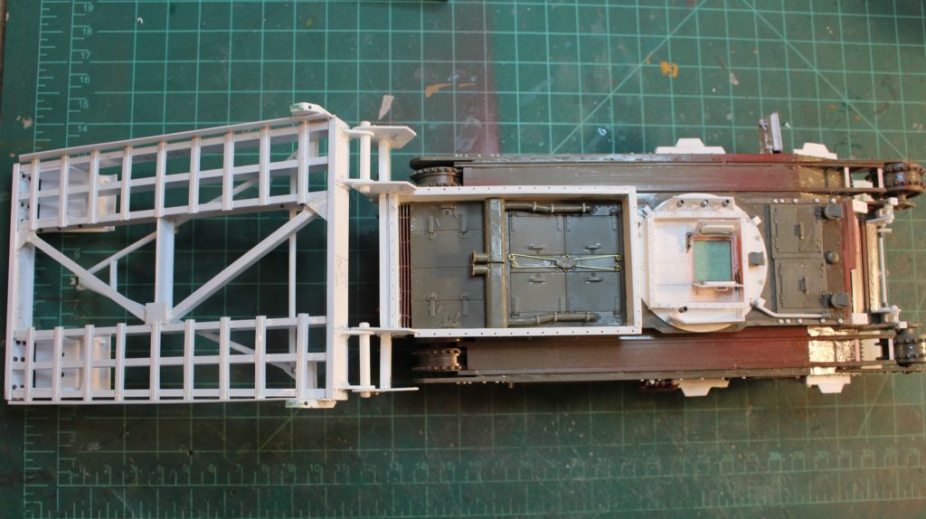
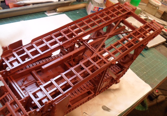
The fixed ramp trackway was scaled to the original dimensions as close as I could get. This ramp has a different construction specifically with the supporting braces to permit access to the engine compartment. Also, at the rear and lining up with the rockets of the forward hinged ramp are rocket exhaust discharge boxes which would have directed the blast and given the forward hinged ramp better upwards momentum.
The next task was to prepare the angled support struts to hold up the fixed ramp. They had to align with the already constructed support braces and the fixed ramp itself. Of course, they did not, so a bit realignment was needed.
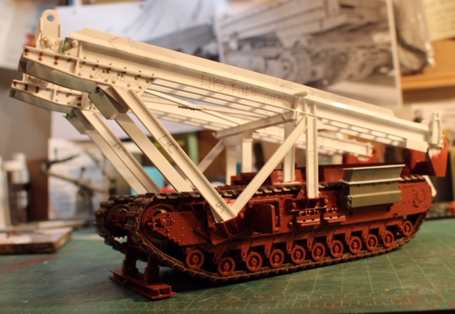
Once in place the fixed ramp was temporarily fitted, after some wrestling, and victory was declared.
This small success allowed work on the forward hinged ramp to begin. Its structure is slightly different from the others as it must be lighter to permit it to flipped over by the rockets – if only I had noticed this earlier. After completing the forward ramp body, I realized that each of the trackways for this ramp is supported by only two long beams not three as the other two are. A rework was needed to correct this minor setback – so close yet so far.
Once the forward ramp was completed in its basic form it was time to put the rocket boxes on ensuring they lined up with the rocket exhaust boxes on the fixed ramp. To be fair this was not as critical as it seemed because the CWM requested that the GER be displayed fully deployed but still they could not be severely out of alignment. The rocket boxes were then constructed and on top of them was added the box-like shock absorbers. I read that the real shocks are steel boxes filled with rolled barbed wire that crush on impact and are replaceable with spare ones carried on the GER.
The true test now, was whether the ramps would fit together … and amazingly they did with a little coaxing.
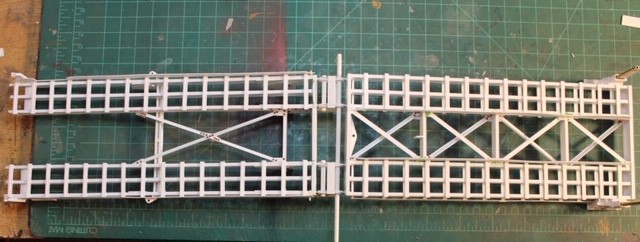
Once the ramps were completed it was time to fit them to the hull. Admittedly, a touch of putty was needed to fully close a few joints, but it fit.
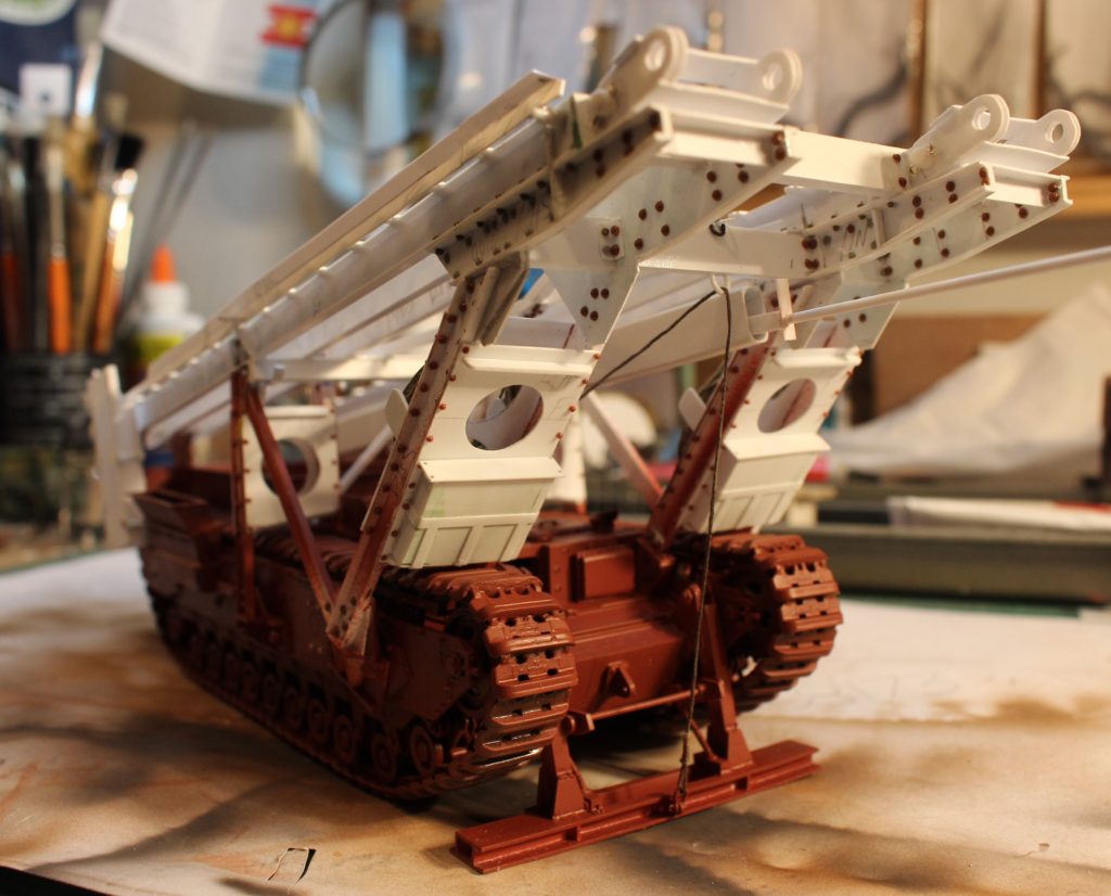
Prior to affixing the ramp the Distance Indicator container box was added. This sits just to the left and overhead of the commander. I confess I had to fudge this part because there were no actual drawings of how it was attached although there were some mysterious weld points on the real GER which I chose to accept. This was a long narrow container and construction was based on drawings and the one good photo from The War Illustrated. Lines simulating cables were made from brass wire and extended from the container down into the small box just to the left rear of the commander’s hatch. These would have been the cables for the pulleys to extend and withdraw the Distance Indicator rod. The supports for the fixed ramp were also strengthened by steel plates which served a dual purpose of support and of carrying spare shock absorbers on the front and large reels of rope, for recovering the ramps, on the rear.
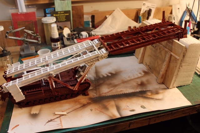
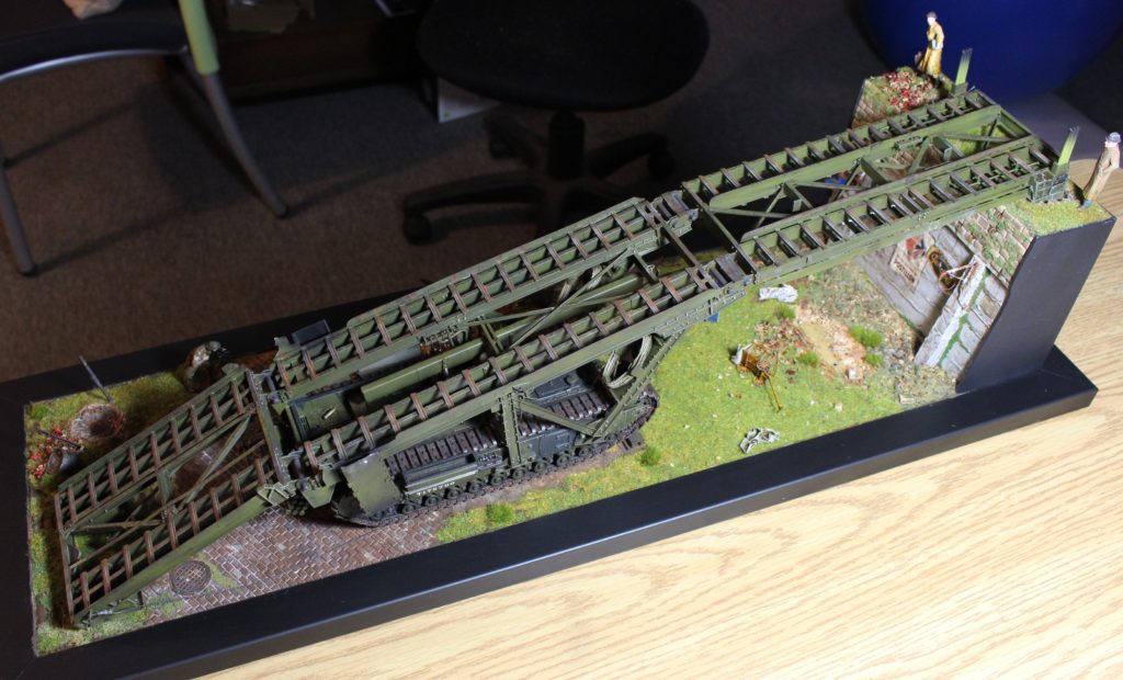
Now with the basic model complete, less painting, it was time to prepare it for the diorama that it was to sit on. It was tested with and without the Distance Indicator rod deployed. The set up worked acceptably and was the basis for further construction.
THE DIORAMA
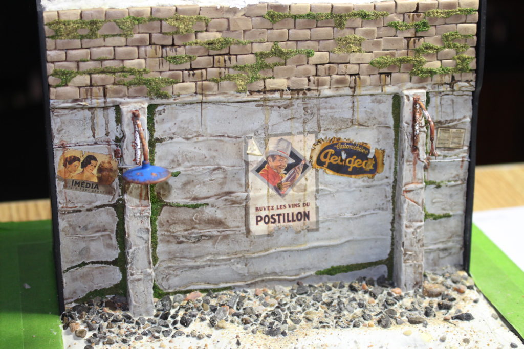
The diorama was staged to highlight the capability of the GER even though she saw no combat. Now this is a big creature and the base was a frame measuring 28 X 8 inches with a light plywood base. The GER model is not heavy but it needed a solid base. An obstacle was needed so a fictional road revetment was built from a block of Styrofoam and the front facing the GER was made from a piece of plaster wallboard with balsa wood supports (literally stuff laying around). The wallboard was then coated in plaster and moulded and painted to look like concrete. A few posters and some electric lights were added for interest. This feature was boxed in heavy plastic and the sides were painted to match the frame.
Once the obstacle was secured on the board with glue and screws the rest of the base was finished. A commercial section of cobblestone road was painted and weathered and glued to the base and the rest filled in with air drying clay.
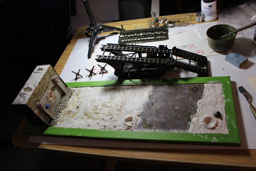
A couple of shell craters and a small ditch were added and filled with acrylic water. Scale model luggage was strewn about, and several tank obstacles were added. The base was then dusted with several layers and colours of Static Grass. After a lengthy drying time, the Great Eastern Ramp herself was bolted to the base and several figures added to give the scale to this monster.
FINISHING
The GER the CWM is fairly scratched up and rusted in places but still retains what I believe to be her original finish of UK SCC15 Olive Drab. It was important for to keep the weathering to a minimum for two reasons: firstly, the GER had just arrived in theatre and secondly, I wanted as much detail as possible to be seen. The vehicle was pre-shaded with flat black to get some colour tones. I used several Tamiya paints to create my primary colour and then highlighting was done with a dry brush. Once this was done, I added some water colour oil stains and a bit of dirt to certain areas. Rust was applied to the tracks and the hinge joints of the ramps and a raw steel acrylic paint was brushed to highlight wear. On top of that I used graphite to give it a metal appearance. The whole model was then sprayed in acrylic floor wax to seal it and allow a base to add decals. There are no markings on the CWM GER but with the help of the Miniature Armoured Fighting Vehicle Association (MAFVA) Churchill registry her number was confirmed and applied it to the sides. I then added the 79th Armoured Division sign and the RE unit and sealed the decals with floor wax. A thin wash of burnt umber oil paint was applied to tone everything down. The figures, tank obstacles and luggage were painted with Tamiya and Vallejo acrylics. The clay base of the diorama was painted with various shades of liquid pigments before the application of grasses and debris. The project was then ready for delivery [large sigh of relief] … after about 5 months of research and construction.
MODEL RESOURCES
- AFV Club Churchill Mark III (Dieppe Raid)
- Evergreen Plastic forms of all types
- Brass wire and tubing
- Tichy Train Group bolts and rivets of several sizes
- Tamiya Red Primer and bottled paints
- Vallejo acrylic paints
- MiniArt models and accessories – cobblestone road, luggage and tank barriers
- DAS air drying clay
- Woodland Scenic Realistic Water
- War World Scenics static grasses and applicator
- Peco Scene Static Grass
- Major (Retired) Don Allen, CD, BA, 8th Canadian Hussars (Princess Louise’s)